Friday 29 November 2013

PRS SE Custom 24 - adding an internal Roland pick-up kit

PRS SE CUSTOM 24

This will be my third Roland GT3 pickup kit install. The Epiphone SG was the first and worked out OK. The Ibanez RG was the first time I took a router to what was, essentially, a new guitar and was a very neat install. The PRS was brand new (I bought it 4 weeks previously) and had a high gloss finish so it was a new challenge. I've tried to add a bit more detail in describing this installation and some of the points that need to be considered whichever guitar you end up choosing. This page is a bit more wordy than previous ones as I jotted down the details whilst I did each stage of the installation. I reckon this will be the last one I do for a while so wanted to capture everything, including some of the thought processes, I went through.

SELECTING THE GUITAR
The original PRS SE Custom 24 - in orange
This is the 2011 "Student Edition" model, made in Korea, that has been heavily discounted in the UK. I'd already tried one a few weeks back in GuitarGuitar in Epsom and was impressed with the feel of the neck and the resonance when unplugged. I couldn't decide which colour looked best so didn't end up buying one that day.  A month later and the price had dropped a further fifty quid so this time I went back and bought a rather striking orange one. One of the advantages of the 2011 model, if you're thinking of fitting the GT3 kit, is the flat top which makes installation easier. The only feature I don't like are the control knobs.

Why choose this guitar - it's a good balance between cost , build quality and playability. At the level at which I play I have no need for a 3 grand, or upwards, Les Paul and even if I did  I think it unlikely that I would take the plunge and fit a Roland pickup so this PRS budget model meets all my requirements including 24 frets, a whammy bar and a very nice neck/action.  If I screw up during the installation I haven't lost a huge amount. This guitar will be used mainly for driving a Roland GR-55 and a Roland GR-33 through a US-20 so the sounds from the conventional pick-ups are not the main priority. Having said that both the PRS and the Ibanez sound good as straight guitars.


HOW EASILY CAN THE PICKUP BE FITTED?


If you are adding a Roland pickup you could have it done professionally and I'd recommend that's the way to go if you are thinking of modifying a much loved guitar. I prefer to do it myself as I can make any last minute changes in positioning switches etc.
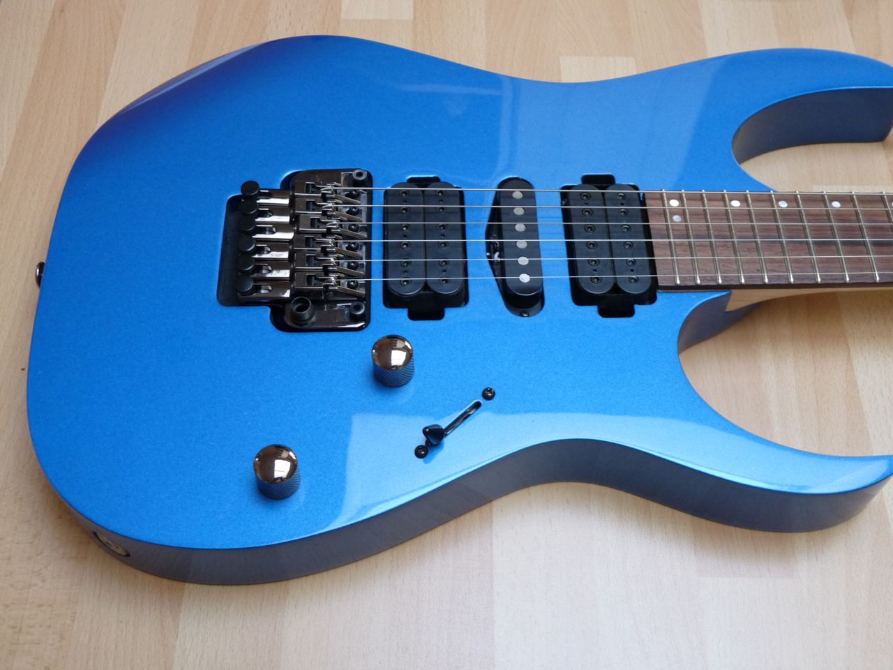
The Roland pickup fits between the bridge and the bridge pick-up
It may be stating the obvious but when choosing a guitar make sure that the Roland pick-up will fit between bridge pickup and bridge otherwise there could be a lot more work required.The dimensions are available on the Roland website so I simply cut a strip of card 8mm wide and took that around with me when looking at prospective guitars. Roland recommend that there is no more than 20mm between their pickup and the point at which the strings come over the saddles/bridge so that's something else to consider. Also check that action of whammy bar doesn't bring the strings so far down that they touch the Roland pick-up or accept that, if they do, you will need to temper your technique to avoid huge dives. With this PRS the Roland pickup fits perfectly.

Ideally you would take off the backplates and the jack socket mount to have a look at the cavities to see if there is sufficient room for the switches, sockets and circuit board. I think it's unlikely that your local guitar shop will allow you to do that but they may have a guitar tech on site who has already carried out a similar installation on your chosen guitar. Failing that do a search on the internet to see if anyone else has tried it or ask a question on the VGuitar Forum.

If you are considering modifying a guitar which has all it's wiring mounted on the scratchplate it is essential you have a look at the cavity to assess if everything will fit or how much enlarging work you will need to do on the cavity. You may also have a problem fitting all the controls without having to make a new scratchplate. I've not tried making one but I'm told it's very difficult to get a professional looking edge without using a router.

For this PRS the bare minimum of work that you would need to do would be - drilling the control switch holes, enlarging the hole for the socket and soldering some switch connections. Routing is optional.

BEFORE STARTING INSTALLATION

Before you start the installation take photographs and draw up a wiring diagram so you can put it all back together again if required. Plan out exactly where everything is going to be positioned and draw up a template. Work out best location for the two push button switches, the toggle that selects guitar, synth or both and the synth volume control. Decide whether you want to install the LED. It doesn't do anything except light up when connected to a powered up GR device.

I didn't want to end up having to rout larger control cavities and making new backplates so I positioned the new controls in such a way that they would fit within the existing cavity. It did mean that I had to compromise on the spacing of the switches but I felt that it was a reasonable trade-off against making the installation a lot easier. You need to remember not to position the switches too close to the cavity edges otherwise you might end up having to do some extra trimming away. To ensure they would fit I cut a piece of card which fitted exactly inside the cavity and then used it to mark out the positions.


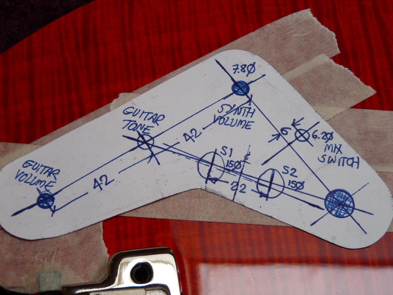
Template for installing the new controls
Before you starting any physical work I protected the guitar body, and in this case the set neck, with plenty of masking tape and padding (bubble wrap).

OUTPUT PLATE


I like a combined output plate. By having the two sockets mounted side-by-side it makes it easier if you want to run two cables together - a 13 way + conventional jack lead. An output from guitar pickup can be taken from back of the GR unit but the signal passes through some circuitry and the consensus of opinion on the VGuitar Forum is if you want a straight guitar output run a separate lead from the guitar's standard jack socket.


Combined output plate
I made the plate from some scratchplate material, drilled the holes and then immersed it in hot water so I could bend it to match the curve of the guitar body. I like the socket plate to be recessed, hence the use of a router to make the necessary inset.  It would be possible to lay the plate on top as an alternative.

The mounting plate for the 13 pin socket that comes with the Roland kit is drilled so that the pcb is mounted parallel to the guitar body. I have found it easier to turn the socket through 90 degrees, as shown above, as it allows the two sockets to be mounted closer together.


ROUTING

If you are prepared to mount the output plate proud on the body then you do not need to do any routing, so skip to the next section.

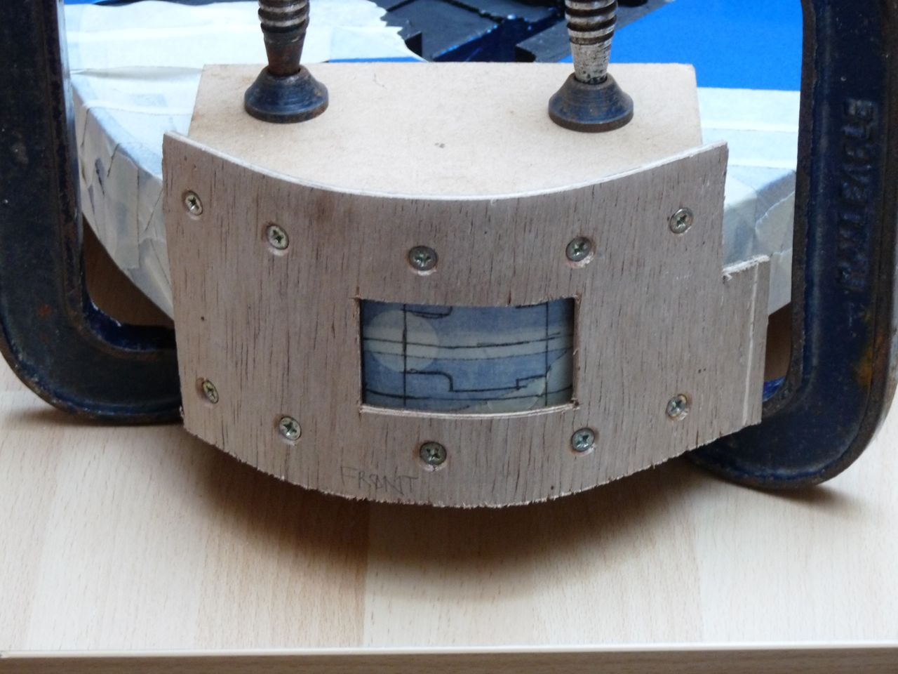
Being a set neck mean it's more awkward to handle the guitar whilst routing and drilling so I wrapped it up well to prevent damage.

I used the guide I made for the Ibanez install, took it apart and re-cut the sides to match the body shape of the PRS. Before clamping the guide onto the guitar I made sure that the body was well protected with masking tape.


Routing guide clamped in position
Depending upon the design of the router you are using you may need to pack the guide off of the body. It depends upon the depth of the collar which is around the cutter. I needed to add some small pieces of plywood underneath to get the right spacing.


Underside of router showing collar around bit
Underneath of the guide showing the packing pieces
Rather than mount the guitar on a work bench I find it easier to hold the guitar between my knees when routing or drilling. Obviously you need to be carefull that you don't slip with the router but by using the guide that really shouldn't happen.

When routing the inset I did several runs with the router, increasing the depth slightly each time, until it was deep enough that the plate is flush with the body.

ENLARGING THE HOLE FOR THE SOCKETS

With the routing completed I set about enlarging the jack socket hole to accommodate the two sockets. The plastic jack socket will fit into a 22mm hole so the first action was to drill this hole using a flat wood bit next to the existing hole.


First stage in enlarging the hole through the body
On previous installations I have then used a rotary file to bring the hole up to the required size. You have to put a lot of pressure on the file for it to cut the wood but that increases the risk of slipping and damaging the body.  I keep the guide in place for added protection to the body.

This time I decided to try a different approach so sharpened up my chisels and used them to carefully pare away the rest of the hole so that the sockets, mounted on the output plate, slotted neatly into the hole and that the plate would sit flush with the guitar edge. Using chisels enabled me to be far more controlled than with the rotary file and the body wood carved very easily. I will certainly use this method again.
 
The enlarged hole to take the two output sockets
I suppose a professional would use a router to enlarge the hole, as it would give a very neat finish, but would mean making a further guide. The drill/chisel method works well and nobody will see the untidy interior once the output plate is in position. I removed the masking tape from the edges of the recess to see how good a finish I had achieved. Not bad. Just a little overcut in the bottom left corner and a small wobble on the bottom face. When I checked my guide it too had these slight anomalies so the quality of the finished recess really does depend on how well the guide has been cut.

 FITTING THE SWITCHES


The biggest challenge with this guitar was stopping the high gloss finish from cracking around the drilled holes. Masking tape alone is usually not enough. You can make up a template in MDF and clamp it tightly in place then drill through that. The fallback position if your do damage the surface finish is to fix a thin scratch plate over the area and make it look like that's what you intended all along. This can also be the solution if you decide to remove the Roland pick-up at some stage and you would be left with a guitar full of redundant holes.

The first hole I drilled was a 6mm one for the mini toggle switch. I decided to try it with just masking tape but used a bit designed specifically for wood and was surprised that it gave a nice clean cut through the gloss finish. I then tried an 8mm hole using a conventional HSS drill but that was not a success and the finish started to crack. Because it was for the guitar tone control I knew that the nut on the potentiometer, mounted with a washer under it, would mask the damage and stop the finish coming away any further. The knob also masks the area. The last two holes were for the S1/S2 up/down switches which are push fit. They require the largest holes of all - 15mm. For these I drilled an 8mm hole using a wood bit and then carefully enlarged them to the required size using a conical rotary file. The rotary action leaves a smooth finish around the hole and any small imperfections are masked by the lip around the switches. If you are using a rotary file then don't try and get to the finished size in one go. As you approach the correct diameter offer up the switches to see if they will fit. You don't want to end up with a hole that is too large and the switches rattling.


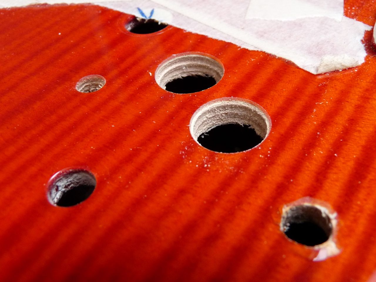
Control switch holes - note damage to finish around front one
 CONNECTING UP

Once all the switches had been installed it was time to make the connections. Depending upon your soldering skills you may decide it's easier to connect the components before fitting them into the cavity. Some of the connections are terminated in mulit-way sockets but the ends to be soldered are stripped back/tinned ready but are a bit on the long side. For neatness you might decide to trim them back but I tend to leave them as they are as there is plenty of room in the cavity to accommodate them as they are and once the backplate is fitted you should not need to disturb them again.


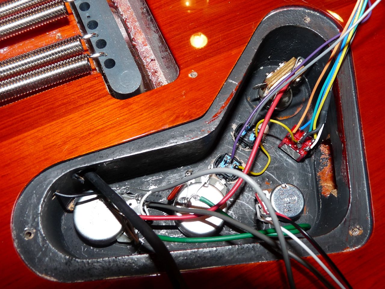
Switches in position and the soldered wiring complete (except pickups)
Once all the soldered connections have been made and the output socket plate fixed in position you can plug the multiway cables into the pcb.


Hard wiring completed and pcb plugged in
You also need to hide the cable when it leaves the pick-up and passes into this hole. How you do it really depends on how high your strings are above the body.  Ideally you would simply line the cable up so it runs directly under the pick-up but if you have insufficient height you can either rout a slot under the pickup or leave the cable exposed for a short distance. The last couple of centimetres have no sleeving around them so look a little ugly.

 FITTING THE PICK-UP UNIT


One area that can cause difficulties is how to route the cable from the GK into the control cavity. The cable has a multiway plug on the end of it and whilst it is possible to fold the cable so the plug runs parallel, it still requires quite a large hole to pass through.  As a last resort you could unsolder the plug, pass the cable through a much smaller hole, and then resolder. I haven't tried it so don't know how difficult that would be. If you choose this way then make sure you draw a diagram and take a picture of the connections. Luckily on this PRS the existing hole that takes the conventional pick-up leads is just big enough for the plug to pass through.

The output cable from the GK has a multi-way connector on the end
Another advantage this PRS has are the pickup mounts. On my Ibanez RG the pickups mount directly into cavities, without mounting bezels, so there is no opportunity to hide the Roland pickup cable. With the PRS you can notch the bezel to slip the cable through without having to make a hole in the top of the guitar and risk damaging the surface.

The multi-way cable fed through the pick-up cavity
Pick-up surround notched to allow multi-way cable to pass into the cavity
The sequence for fitting the GK was to notch the bridge pick-up mount. Tape the GK temporarily into position and feed the cable into the control cavity. Do the same with the conventional pick-up leads. Fix the pick-ups into position and solder the leads onto the conventional selector switch.

To ensure that the GK was correctly lined up I restrung the guitar and moved the GK until it was exactly symmetrical with the strings, then marked the two mounting hole positions. I drilled two 1.5mm holes, then increased the bit to 2.5mm and finally used a 3.0mm for the first 15mm of the hole. By gradually increasing the bit size I was able to drill the holes without damaging the surface finish.

(When fixing the pick-up into position the easiest way is too simply screw the two support screws directly into the body. The "Rolls Royce" way to do it would be to install two, small, threaded bushes into the body and then use small bolts to hold the pick-up in position or you could make a thin plate that fits under the rear pick-up bezel. I chose the simple method)

To keep the GK at the correct height Roland include two springs, about 25mm long, which fit over the mounting screws, between the GK and the guitar body. They were too long for this installation so I cut them in half and that was just right.

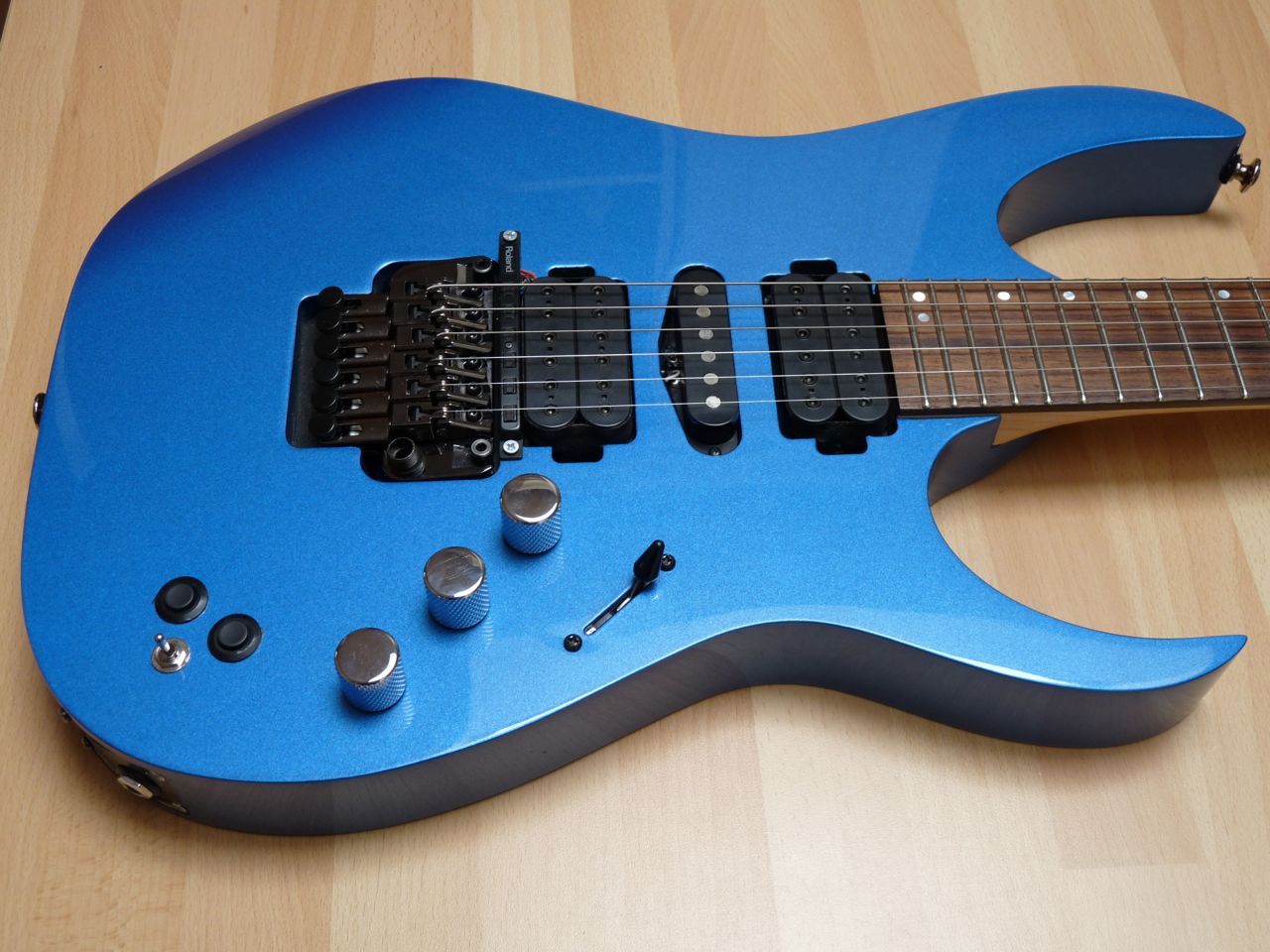
Installation complete. I couldn't find any suitable knobs so took them off of my Ibanez as a temporary measure. I quite like the chrome look so will have to search round to get some more, maybe be a little smaller though.

Ready for testing! Plug the GK cable into the GR-55 and see what happens. All as it should be so time to put all the tools away and play.

 Here's the finished guitar. I reckon it looks pretty neat and would recommend it as a "not too difficult" project.

The finished guitar
If you have any questions, want some specific dimensions or advice please contact me. For general information about vguitars, guitar synthesisers etc. then join the best forum around - http://www.vguitarforums.com

Ibanez RG870 - adding an internal Roland pickup

Having added a Roland GT3 pickup kit to an Epiphone SG and been happy with it for quite a while I decided to get myself a more advanced guitar. The selection criteria were 24 frets , a locking tremolo and sufficient room behind the bridge pickup to fit the Roland hex pickup.  I knew I'd probably be looking for a "metal" orientated guitar and after a lot of trying out guitars in Denmark Street in London and then GuitarGuitar in Epsom I settled on an Ibanez RG. The one I really like has the flamed top but I didn't want to spend that sort of money if it then proved very difficult to install the GT3. I had a look on eBay and found a metallic blue one that eventually I won for about half the new price. When it arrived it really was as described - it looks completely unplayed with no blemishes or scratches at all and in a very nice semi-rigid case.


Original Ibanez RG870
First thing to do was remove the neck and all the hardware to leave just the body. Next I removed the backplates to see what options there were for installing the various parts of the GT3 kit and take some photos so that if something gets disconnected you know where it goes back to.

Ibanez RG870 Cavities
My first impression was "this doesn't look very encouraging" as the cavities looked too small but after a bit of thinking I came to realise that because of the jack socket cavity size it could actually be quite a simple installation with no need to rout new body cavities. I carefully measured the various components and did a rough sketch to confirm how big the cutout for the  "output" plate would need to be.


Working out the output plate dimensions
I realised that it would be possible to mount the 13 pin and jack sockets adjacent to each other on one plate. (The jack socket pictured here is the one that comes fitted to the RG. I had intended to re-use it but in the end it proved too long. More of that later). 

This next operation took the longest of all, not because it's particularly difficult, but because I had to pluck up the courage to attack my new guitar with a router. To ensure the router went where it was supposed to go I decided that some form of guide was essential. I marked out and cut two sides from MDF and joined them together using thin plywood which had an  opening of the required size cut into it. I then protected the guitar body with masking tape  before clamping the guide into position.


Router guide clamped in position
Once I had made the first router cut I found that it was actually a lot easier than I thought it would be and that the guide very effectively prevented any overcut. I reckon the final result isn't bad for a first attempt. For the plate itself I used some scratchplate material that I had bought for another project. Once cut to the right dimensions I immersed it in boiling water that softened it enough to allow it to bend to the shape of the guitar.


Rout for plate completed and plate bent to shape
The hole through to the cavity can then be cut. I kept the router guide in place and used a jigsaw to make the opening. I then drilled the holes in the output plate to make sure that the two sockets would fit correctly. It was at this point that I realised that if I made the plate slightly larger it would make fitting the various wires much easier so I went through the whole process again to accommodate another 8mm on the plate.


Hole cut through to cavity
One last thing to do before starting to try out component fit was to drill a larger hole between the main cavity and the jack socket cavity. There are a lot of cables/connectors that need to pass though here so I ended up enlarging the existing hole to 12mm.


Two multiways go to the sockets + wiring to jack socket and switches
Next it was time for the bit which, in hindsight, I found the most difficult, drilling holes without damaging the guitar's paintwork. I thought that simply protecting the surface with the masking tape would be sufficient but the finish still chipped away. In the end I resorted to marking out the holes onto MDF first and then clamping this to the body and drilling though it. Better than masking tape but still not perfect. Luckily the flanges on the switches cover the worst of the damage. (My fallback position if the paintwork really did finish up looking bad would have been to fit a scratchplate over the offending area)

Because Ibanez had already provided a nice, wide cavity for the jack socket it was possible to fit both the up/down push switches and the output select toggle into the existing space. Having drilled the holes, I inserted the switches in their respective positions and then tried fitting the plate with the two sockets on. It was at this point that I realised the original Ibanez jack socket was clashing with the selector switch. A quick search in my spares box found a much shorter socket and I used this instead. 

Time to get the soldering iron out and make the common connections between the switches and then the lead to the jack socket. This proved quite tricky. You will need a soldering iron with a fine tip and a steady hand. The rest of the wiring can then be threaded through the hole between the cavities, the final connections to the selector switch soldered and multi-pin connectors snapped into place.  There's also the synth volume control to be added into the main cavity and plugged into the PCB.


Synth/Guitar selector switch wiring
Main cavity wiring
Before doing anything else I plugged the guitar into my GR-55 to check that the switches were working correctly. All was OK so the conventional pickups could be refitted, having first taken the Roland pickup lead through the pickup cavity and into the main cavity. I didn't want to permanently fix it at this stage as I needed to restring the guitar to check clearances.

The wood between the rear humbucker cavity and the rout for the tremolo system is 8mm, exactly the same as the pickup. Once I'd  refitted the tremolo block and restrung I found that the pickup could be screwed directly to the guitar body without any need for packing but I think I may need to review this once I'm properly set up. Looks like I might need to bring the  pickup up a few mil.


Here's the completed project.


The finished Ibanez RG870
A few finishing touches are still needed. The edges of the routed hole need painting black, as do any silver coloured screws and the three, large chromed control knobs need to be replaced with original Ibanez ones (once I can get hold of a third knob for the synthesiser volume) as they are too large. I'm toying with adding an LED but not until I've worked out how to drill holes without damaging the finish.


In many ways the RG870 has proved to be the ideal guitar for adding the Roland pickup to. It has not required any additional cavities to be routed and therefore no new backplates. The existing jack socket cavity is large enough for installing the switches and there is just the right amount of space for the new pickup. The main cavity has plenty of room for the additional volume control and the Roland PCB just fits in.

I'm pleased with how this project has worked out. If I can crack the hole drilling problem then I might just treat myself to the flame topped RG870 that I saw in the guitar showroom.

RG870's in GuitarGuitar, Epsom
If you have any questions, want some specific dimensions or advice please contact me. For general information about vguitars, guitar synthesisers etc. then join the best forum around - http://www.vguitarforums.com

Epiphone SG - First attempt at fitting a Roland GT3 Kit

BACKGROUND

I'd been toying with the idea of getting a guitar synthesiser for a few years and finally decided to take the plunge to give myself something to do whilst recuperating from an operation. I found a Roland GR33 at a reasonable price on eBay but it didn't have the pickup with it. The choice was then to look out for a GK2 or GK3 removable pickup and fit it to one of my existing guitars or to buy a GT3 permanent installation kit and have a go at fitting it.

I decided that rather than fit a semi-permanent pickup I would go the whole hog and dedicate a guitar for use with the synthesiser so started looking around to see what might be suitable for a fairly simple installation that didn't involve the use of a router. I've got one but my skills using it are limited.

The pickup and the 13 way cable were ordered from DV247.com and arrived the next day. (I've bought a number of bits and pieces from them and have been very pleased with the value for money and the speedy delivery).

I found a couple of pages on the web showing how the installation is done professionally on a Strat and it looked a bit scary. I decided that I would look around for a fairly cheap second hand guitar which I could modify accordingly and if I did make any mistakes, slip with the drill etc then nothing expensive would be lost.

I settled on a basic guitar that didn't have a high gloss lacquer finish (which would be very easy to damage), had a simple pickup layout, no tremolo unit and a plain front ie. no scratchplate.  Two guitars that matched these criteria were the Epiphone Custom SG Special and the Epiphone Les Paul Special. I had another look on eBay and found an Epiphone Custom Shop SG. I'm not a guitar connoisseur but I've very pleased with the guitar that I've ended up with. The action is not bad, it is not too heavy, balances well, and sounds good.

THE ORIGINAL GUITAR
Epiphone SG - before the  modifications
Epiphone SG - Original wiring
THE MODIFICATIONS
I started by removing the strings, the neck and all the hardware, having first taken a picture of the original wiring. You'll need to be confident using a soldering iron for this bit and the reconnection later.

My biggest concern, before I started, was how to get the cable from the hex pickup into the controls cavity. From the picture below you will see that the pickup cable has a pre-wired multiway connector fitted. I was toying with the idea of removing the connector and then refitting once the cable was in position. As luck would have it the hole that Epiphone had drilled between the pickup cavity and the control cavity is just big enough for the cable, with its connector, to pass through. That was a major headache out of the way. I had to nibble a small indent at the back of the pickup cavity so the hex lead could pass under the humbucker surround but that was all.


Roland GT3 Kit
The contents of the Roland GK3 internal installation kit are shown above. Most components are connected using pre-wired multiway connectors. The only soldering that is required is an earth wire which connects to the common terminals of the switches and the guitar output from the original jack socket.

The next big decision was the exact layout for each of the controls and the placement of the 13 pin socket.  The original guitar had one volume and one tone control working across the pickups. I decided to dispense with the tone control and use the redundant hole to take the synthesiser volume control. I then marked out the remaining 3 switches and the LED accordingly, using masking tape, and drilled the correct size holes. The patch change buttons are both push fit, the toggle and LED are held in place with nuts and washers.

Probably the most daunting task was marking out and then cutting the hole for 13 pin socket. At this point one slip with the drill could do serious damage so it's worth taking your time. I decided to "stitch" drill a series of small holes around the edge of the hole and then join them up to give me the large, rectangular hole finally required.

Marking out for the new 13 pin socket
Socket hole drilled out
I used a file to finish off the hole but it doesn't need to be too tidy as the socket mounting plate hides it.  The mounting plate has plain holes drilled in it which means that the fixing screws would stand proud from the surface. I very carefully countersunk each of them and then fitted the plate with the smallest crosshead screws that I could find.

New socket installed
New control layout
I was now ready to mount the hex pickup which is supported by two wood screws and springs. You adjust the pickup by screwing them in to the right height. The Roland instructions show you what tolerance you need between the pickup and the strings to get the optimum performance. There a small grub screw in the middle of the pickup so that a degree of curve can be introduced to match the guitar stringing.

The final task is the internal wiring. There are a number of soldered connections which need to be made first and then the motherboard can be plugged in using the multi-way connectors. The circuit board is very small and insulated by a plastic wraparound. Once plugged in it can be turned over, laid into the cavity and the backplate fitted.

New wiring with multiway connections to PCB
The pcb fits nicely on top of the controls
It's then time to see if you've managed to install it correctly. I'd had my GR33 for 3 weeks before I modified the guitar and had been unable to try it out so it was double anticipation. It was with a certain amount of trepidation that I plugged in the guitar and switched on the synth. It worked first time and I was playing a Hammond, from the guitar. Amazing!

THE FINAL RESULT

Epiphone SG - Original
Epiphone SG - Modified
As a finishing touch I added a couple of new speed knobs. I'm really pleased with the final result as the guitar still retains it's classic, uncluttered appearance.

If I was a better guitarist I would also include a sound file but I wouldn't inflict that on anyone. Suffice to say that the in-built Roland sounds are pretty decent. Bearing in mind the GR33 unit is some 10 years old then the sounds can be described as "classic".

Using a midi-to-USB cable the GR-33 can be plugged into a Mac and used to drive software instruments. This opens up all sorts of possibilities. I've been using it with Garageband to drive G-Force's M-Tron Pro software which gives me all the classic Mellotron sounds from my guitar fretboard. The only thing to watch out for here is latency, ie the time it takes for the computer to process the incoming signal and send it to the soft instrument. So far it's not been too bad but I wonder if rather than using a cheap midi-to-USB cable a more expensive unit would give better performance.

Some guitar synthesiser users seem to suffer from tracking problems and unwanted notes. I think if you start with the attitude that whilst this is pretty amazing technology it isn't perfect then you will not be disappointed. By setting the tracking parameter in the voices to match the instrument being played ie. if you are playing a keyboard voice then set the tracking to semitones to match the keys, then this will help produce a realistic sound.

I hope this information has been useful. Any questions then please contact me.

Monday 14 October 2013

Welcome

Here's the new location for my pages on Midi guitars. I've moved them from their original blog as I had run out of space and this gives me the opportunity to post some pages solely devoted to guitars and guitar synthesis.

To start off with you will find the original pages on how I went about adding the Roland GT3 internal kits to an Epiphone SG (something cheap and cheerful to learn on), an Ibanez RG870 and finally a PRS SE Custom 24. Over time I'll add some details of what they are plugged into (currently a Roland GR-33 and GR-55 via a US-20).